 English
 中文简体
中文简体
 русский
Inlet Thread: M30x1.5
Outlet Thread: G1/8x28
Gauge Connection Thread: M10x1x12.5
Dip Tube Thread: M16x1.5
Content
Cause of fault
Internal mechanical damage: The gears, hairsprings, or spring tubes inside the pressure gauge are deformed or broken.
Impurity blockage: Rust, scale, or foreign matter in the pipeline enters the pressure gauge and jams the pointer mechanism.
Overpressure shock: The system pressure exceeds the range instantly (such as the water hammer effect), causing the mechanical parts to deform.
Potential risks
The inability to monitor the system pressure in real time may delay the start of the fire protection system or the fault alarm.
Misjudgment of the system status leads to safety hazards.
Solution
Tap the case: Tap the case with a rubber hammer to try to loosen the stuck pointer (temporary emergency only).
Disassembly and cleaning:
Close the valve, remove the gauge head after venting the pressure.
Clean up the internal impurities with alcohol or a special cleaner.
Replace a new gauge: If the internal gears or spring tubes are damaged, it is recommended to replace them directly (the repair cost may be higher than that of a new gauge).
Cause of failure
Aging of the seal ring: After long-term use, the rubber seal ring hardens and cracks.
Case damage: External impact or corrosion causes cracks in the case.
Oil evaporation: High temperature environment causes silicone oil to gradually evaporate and the liquid level drops.
Potential risks
After oil leakage, the pointer damping fails, and the readings shake or are inaccurate.
Oil stains may contaminate fire pipes or equipment.
Solution
Replace the seal ring:
Remove the gauge head and replace the oil-resistant rubber seal ring (must match the original factory specifications).
Refill silicone oil:
Use high-viscosity silicone oil (such as DC200) and fill it to the standard liquid level through the oil filling hole.
Overall replacement: If the case is broken, a new gauge must be replaced (select a protection level of IP65 or above).

Cause of failure
Ultraviolet radiation: Long-term direct sunlight causes the dial printing to fade.
Chemical corrosion: Acid-base environment or detergent erodes the dial coating.
Water vapor penetration: The humid environment causes the dial to fog and mold.
Potential risks
It is difficult to accurately read the pressure value, affecting the operation judgment.
It may be mistaken for the dial to be damaged, resulting in unnecessary replacement.
Solution
Cleaning the dial:
Use a soft cloth dipped in alcohol to gently wipe to avoid scratches.
Replace the dial:
Contact the manufacturer to provide the same model dial (some pressure gauges support separate replacement).
Add a protective cover:
Install a UV-proof acrylic cover or metal sheath.
|
Fault phenomenon |
Possible cause |
Solution |
|
Pointer does not return to zero |
Fatigue of spring tube, bending of pointer shaft |
Calibrate or replace with new meter |
|
Reading jumps |
Pipeline vibration, insufficient oil |
Reinforce installation, add oil or install buffer valve |
|
Water accumulation on dial |
Poor sealing or condensation |
Replace the sealing ring and keep the environment dry |
Inspection items
|
Inspection content |
Standard requirements |
Abnormal handling |
|
Pointer flexibility |
Tap the case lightly, the pointer should swing slightly and then return to its original position |
If it is stuck, it needs to be cleaned or replaced (refer to the troubleshooting guide) |
|
Dial clarity |
Scales and numbers are not blurred or faded |
Clean or replace the dial |
|
Sealing (oil-immersed table) |
No oil leakage, the liquid level is not lower than the standard line |
Refill silicone oil or replace the sealing ring |
|
Connection status |
No rust, looseness or leakage |
Tighten the bolts or replace the gasket |
|
Environmental adaptability |
No direct sunlight, high temperature or corrosive gas |
Install a protective cover or move the installation location |
Calibration method
Close the valve: isolate the pressure gauge from the system and exhaust the residual pressure.
Connect the standard gauge: use a standard pressure gauge with higher accuracy (0.25 grade or above) to compare the readings.
Pressure test: gradually apply 25%, 50%, 75%, 100% of the range pressure and record the error.
Allowable error: ≤±2% of the range (such as 1.6MPa gauge, the error must be ≤0.032MPa).
Adjust or replace: If the error is out of tolerance, try to adjust; if it cannot be repaired, replace the new gauge.
Note
The calibration must be performed by a certified person and records must be kept.
The digital pressure gauge needs to check the status of the sensor and display simultaneously.
Temperature and humidity
Avoid high temperature: ambient temperature ≤60℃ (high temperature will accelerate the volatilization of silicone oil or the aging of mechanical parts).
Moisture and condensation prevention: use a stainless steel shell (such as 316L material) or install a moisture-proof cover in humid places.
UV and corrosion
Shading treatment: add metal sheath or UV protection cover when installing outdoors.
Anti-corrosion selection: acid-resistant and alkali-resistant coating or all-stainless steel pressure gauges are selected in chemical areas.
Vibration and shock
Shock-absorbing installation: rubber pads or pulse dampers are installed in locations with large vibrations such as pump rooms.
Shock-resistant pressure gauges: oil-filled (glycerol or silicone oil buffer) or spring tube reinforced types are preferred.
Installation location
Easy to observe: installation height 1.5-1.8 meters, avoid dead angles.
Avoid interference: avoid electromagnetic equipment (such as frequency converters), high-temperature pipes or corrosion sources.
Connection method
Buffer device: install a buffer tube ("S" bend) or throttle valve after the pump outlet or valve.
Isolation valve: install a three-way valve or needle valve for easy disassembly and maintenance.

Inlet Thread: M30x1.5
Outlet Thread: G1/8x28
Gauge Connection Thread: M10x1x12.5
Dip Tube Thread: M16x1.5

Inlet Thread: M30x1.5
Outlet Thread: G1/8x28
Gauge Connection Thread: M10x1x12.5
Dip Tube Thread: M16x1.5

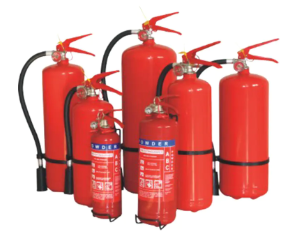
Hanging Dry Powder Fire Extiguisher

inquiry
Can Supply Mature And
Stable Products.
Contact Us
Phone: +86-575-82411708
E-mail: sale@newideafire.com
Address: WUFU INDUSTRIAL ZONE, ZHEJIANG,CHINA
Products
Get In Touch

 浙公网安备 33060402001388号


